

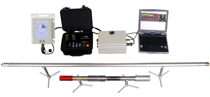
ZT-MWD measurement while drilling system is used for real-time measurement and transmission of borehole trajectory parameters, it features advanced design, reliable performance, high-precision measurement and wide application range. ZT-MWD system, energized by downhole turbine generator, utilizes the positive mud pulse signal to transmit the data acquired by downhole measurement sensor about the well track and the toolface of directional drilling tools.
Technical features
(1) Applicable for all working conditions, such as onshore, desert and offshore operations, deep well and high-temperature well.
(2) Available in all series (4-3/4”;6”;8-1/2”;12-1/4”;17-1/2” specification) to meet the drilling demand in different borehole size and conditions.
(3) With its own generator: more beneficial, economical and safe than that with battery, avoiding waste of battery.
(4) High reliability: long-period continuously stable and safe operation, less restricted by other drilling conditions; reducing the abnormal tripping.
(5) High Compatibility: fully compatible to equivalent well-head MWD/LWD system.
(6) High safety: There are Barrier Box System to separate the drilling floor equipment, thus ensuring the safety and protecting the surface system.
(7) Fast Transmission: tool surface update speed in only 9 seconds.
(8) Short Length:MWD-2.9M
(9) Positive pulse transmission technology: simple and compact structure of tools, easy operation and maintenance.
(10) Convenient operation: constant and fast testing, assembly and disassembly on site.
Main functions
(1) Borehole trajectory measurement: Probe measure the values of accelerometers, fluxgates and temperature sensor, and calculate the borehole trajectory parameters.
(2) Encoding: According to the operating requirements, probe use fixed format or non fixed format to generate the electrical pulses. And then these electrical pulses transferred to pulser.
(3) Power generating: Pulser use the power transferred from impeller to generate electric energy.
(4) Transmission: Pulser generates positive pressure signals under the control of electrical pulses.
(5) Decoding: Transducer acquires the pressure signals generated by downhole system, the signals are transferred through barrier box and DAQ system to surface system. Then surface system decode the signals to real time parameters.
(1)system accuracy
|
Azimuth |
±1.0°(lnc>10°,Dip<70°) |
|
Inclination |
±0.1° |
|
Magnetic tool face |
±1.5° |
|
High side tool face |
±1.5° |
|
Update speed of survey data |
3.5min/2.5min |
|
Update speed of tool face |
14s/8.75s,bitrate 0.5Hz/0.8Hz |
(2)technical specification of downhole tools
|
Hole size |
O.D.of drill collar |
I.D. drill collar |
CommCon length |
Connection |
Max dogleg rate |
||||||
|
inch |
inch |
mm |
inch |
mm |
feet |
m |
Slide Drilling |
Rotary Drilling |
|||
|
4-3/4 |
3-1/2 |
89 |
2.3 |
59 |
21 |
6.4 |
Special |
36°/30m |
36°/100ft |
18°/30m |
18°/100ft |
|
6 |
4-3/4 |
121 |
2.815 |
71.44 |
31 |
9.449 |
3-1/2〞IF |
30°/30m |
30°/100ft |
14°/30m |
14°/100ft |
|
8-1/2 |
6-3/4 |
172 |
2.815 |
71.44 |
6 |
1.829 |
4-1/2〞IF |
21°/30m |
21°/100ft |
10°/30m |
10°/100ft |
|
12-1/4 |
8 |
203 |
3-1/4 |
82.55 |
6 |
1.829 |
6-5/8〞REG |
14°/30m |
14°/100ft |
8°/30m |
8°/100ft |
|
17-1/2 |
9-1/2 |
241 |
3-1/4 |
82.55 |
6 |
1.829 |
7-5/8〞REG |
14°/30m |
14°/100ft |
8°/30m |
8°/100ft |
(3)working conditions for downhole system
|
Mud pump |
Double or Triplex cylinder |
|
Air bag charging amount |
30~40% of the standpipe pressure as recommended |
|
Acceptable mud discharge |
|
|
4-3/4” Hole size |
7~15.8 L /s(110~250GPM) |
|
6”Hole size |
9.50~22.1L /s(150~350GPM) |
|
8-1/2” Hole size |
14.2~41.0L /s(225~650GPM) |
|
12-1/4” Hole size |
22.1~75.7L /s(350~1200GPM) |
|
17-1/2” Hole size |
22.1~75.7L /s(350~1200GPM) |
|
Mud type |
WBM(water or salt water) |
|
OBM(crude oil or mineral oil) |
|
|
Mud density |
Less than 2170 Kg /m3 (18PPG) |
|
Sand content |
Less than 1% |
|
PV |
Less than 50cp |
|
Maximum pressure |
18000Psi(124MPa) |
|
Maximum temperature |
150℃(302°F) |
|
Plugging materials |
Not allowed |